Internal Combustion Engine Vehicle Wiring Harness Explained: A Complete Guide to Power, Control Modules, Fuses and Body Electronics
A modern vehicle depends on much more than an engine and a battery. Behind the dashboard and throughout the engine bay is a complex network of wires, connectors, fuses, relays, control modules and electrical components working together. This guide explains the main parts shown in a vehicle wiring harness overview and how electrical power and control signals travel through the car.
The Electrical Network Behind Every Modern Car
When people think about a car's electrical system, they often imagine the battery, alternator and a few lights. In reality, a modern internal combustion engine vehicle contains a large electrical network connecting dozens or even hundreds of components.
The wiring harness is what makes this network possible.
It carries electrical power from the battery and charging system to different circuits while also transmitting signals between sensors, switches, motors and electronic control units. Without this network, the engine could not be managed electronically, the lights would not operate correctly, and systems such as windshield wipers, fuel delivery and dashboard displays would not function.
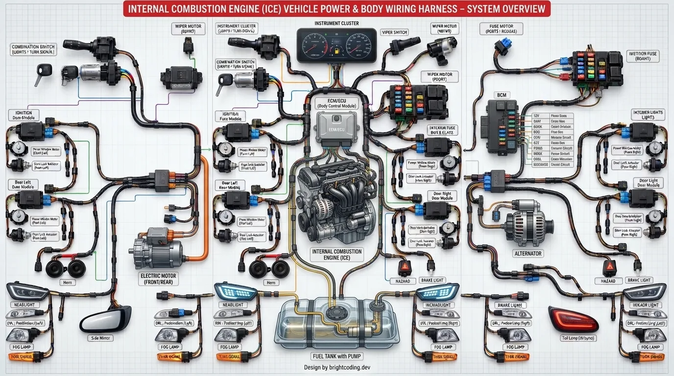
The diagram above provides a simplified visual overview of this architecture. It shows how the engine, body electronics and electrical accessories are connected through a central network of wires, fuses, connectors and control modules.
Let's break it down.
1. What Is a Vehicle Wiring Harness?
A wiring harness is a group of electrical wires bundled together and protected so they can safely connect different parts of a vehicle.
Instead of running hundreds of loose wires throughout the car, manufacturers organize them into sections and branches.
A typical harness can include:
- Power wires
- Ground wires
- Signal wires
- Connectors
- Fuse and relay connections
- Communication lines
- Branches for individual systems
The harness is designed to survive heat, vibration, moisture and mechanical movement.
In the image, the thick black bundles represent the organized harness sections running between the main electrical components.
2. The Engine: The Electrical and Mechanical Center
At the center of the diagram is the internal combustion engine (ICE).
Although the engine is primarily mechanical, modern engines depend heavily on electronics.
Electrical systems help manage:
- Fuel injection
- Ignition
- Engine sensors
- Idle control
- Emissions systems
- Cooling systems
- Electronic throttle functions
- Starting and charging
The engine control unit communicates with many components to determine how the engine should operate under different conditions.
This is why an engine problem can sometimes be caused by an electrical issue rather than a mechanical failure.
3. ECU and ECM: The Vehicle's Electronic Brain
One of the most important components in the diagram is the ECU/ECM, or Engine Control Unit / Engine Control Module.
This computer receives information from sensors and uses programmed logic to control engine functions.
Depending on the vehicle architecture, the ECU can process information such as:
- Engine speed
- Coolant temperature
- Airflow
- Throttle position
- Oxygen sensor readings
- Crankshaft position
- Camshaft position
- Vehicle speed
The ECU then sends commands to actuators and other systems.
This continuous exchange of information happens extremely quickly while the vehicle is running.
4. BCM: Controlling the Vehicle Body Electronics
The Body Control Module (BCM) is another major component shown in the diagram.
Unlike the engine ECU, the BCM generally manages body-related electrical functions.
Depending on the vehicle, it may be involved in:
- Interior lighting
- Exterior lighting
- Door locking
- Windows
- Wipers
- Turn signals
- Central locking
- Horn control
- Alarm functions
- Other convenience features
The BCM helps reduce the amount of direct wiring required between switches and individual components.
For example, pressing a switch does not necessarily send power directly to the final device. The switch may send a signal to the BCM, which then activates the appropriate circuit.
5. Fuse Boxes: Protecting the Electrical System
The fuse boxes shown in the diagram are critical for safety.
A fuse is designed to protect an electrical circuit from excessive current.
If a short circuit or abnormal current condition occurs, the fuse can open the circuit before the wiring becomes dangerously hot.
Typical fuse-box circuits may protect:
- Lighting
- Wipers
- Electronic modules
- Fuel pump
- Horns
- Interior accessories
- Engine management
- Power outlets
A blown fuse should never automatically be replaced with a higher-rated fuse. The correct fuse rating is part of the system design.
6. The Ignition or Combination Switch
The ignition or combination switch acts as an important control point for vehicle power.
Depending on the vehicle, turning the ignition switch can establish different electrical states such as:
OFF → ACCESSORY → IGNITION/ON → START
Each position can activate different electrical circuits.
The starting position may energize the starter control circuit while other systems remain powered to support engine operation.
Modern vehicles may use electronic start authorization systems rather than a traditional mechanical ignition switch, but the basic concept of controlled power distribution remains.
7. Instrument Cluster: Information for the Driver
At the top of the diagram is the instrument cluster.
This is the driver's main source of vehicle information.
It can display:
- Engine speed
- Vehicle speed
- Fuel level
- Warning indicators
- Temperature
- Charging status
- Engine faults
- Turn indicators
- Safety alerts
The cluster does not simply receive power and display information. In modern vehicles, it may communicate electronically with other control modules.
This is why a communication problem in one part of the vehicle can sometimes produce unusual dashboard warnings.
8. Alternator: Producing Electrical Power While the Engine Runs
The alternator is responsible for generating electrical energy once the engine is running.
The battery provides the energy needed to start the vehicle, but the alternator supplies electrical power during operation and helps recharge the battery.
The alternator supports systems such as:
- Engine electronics
- Lighting
- HVAC controls
- Audio systems
- Body electronics
- Charging circuits
A charging problem can therefore affect multiple vehicle systems at the same time.
9. Fuel Pump and Fuel Delivery
At the bottom of the diagram is the fuel tank with pump.
The fuel pump is electrically powered and supplies fuel to the engine's fuel delivery system.
The pump circuit usually includes protection and control elements such as:
- Fuse
- Relay or electronic switching
- Wiring
- Ground
- Fuel pump assembly
- ECU or another control module
When the engine control system determines that fuel delivery is required, the pump is activated according to the vehicle's control strategy.
A failure anywhere in this chain can prevent the engine from starting.
10. Windshield Wiper System
The diagram also illustrates the wiper switch and wiper motor.
A typical wiper circuit involves:
Wiper switch → control module/relay → wiper motor → mechanical linkage
The motor converts electrical energy into mechanical movement, which drives the wiper mechanism.
Modern systems may include several operating modes such as:
- Low speed
- High speed
- Intermittent
- Automatic rain-sensing operation
- Park position
This is another example of how a relatively simple driver control can involve several electrical and mechanical components.
11. Exterior Lighting and Signaling
The wiring harness also distributes power and control signals to the vehicle's lighting systems.
The image includes examples such as:
- Headlights
- Fog lights
- Daytime running lights
- Brake lights
- Rear lights
- Turn signals
Lighting circuits are often split into multiple branches and protected by dedicated fuses or electronic protection inside a control module.
Modern vehicles can also use separate lighting modules or network-based commands rather than direct switch-to-lamp wiring.
12. Horns and Other Small Electrical Loads
The horn circuit is another good example of a simple but important electrical system.
A horn may be controlled by:
Steering-wheel switch → control module/relay → horn → ground
The control method varies by vehicle, but the principle remains the same: a driver input triggers an electrical circuit that activates an electromagnetic or electronic device.
Other smaller loads can use similar protection and switching strategies.
13. Door and Body Electrical Systems
The wiring harness extends far beyond the engine compartment.
Doors can contain their own electrical components, including:
- Door lock actuators
- Window motors
- Door control modules
- Courtesy lamps
- Switches
- Speakers
- Sensors
This means the body wiring harness is just as important as the engine wiring harness.
A broken wire inside a door flex area, for example, can cause intermittent electrical problems that are surprisingly difficult to diagnose.
14. Electric Motors Throughout the Vehicle
Several electric motors appear in the diagram.
Depending on vehicle design, motors can be used for:
- Windows
- Wipers
- HVAC functions
- Seats
- Mirrors
- Cooling fans
- Power accessories
Each motor requires appropriate power, grounding and control.
A motor that fails to operate does not automatically mean the motor itself is defective. The actual problem may be a fuse, relay, wiring issue, bad connector, switch or control module.
15. Why Ground Connections Matter
One of the most overlooked parts of automotive electrical diagnosis is grounding.
Electrical current must have a complete path through the system.
A typical circuit can be simplified as:
Power source → fuse/protection → switch/module → load → ground → power source
A poor ground connection can cause:
- Dim lights
- Intermittent electronics
- Slow motors
- False sensor readings
- Module communication problems
- Starting difficulties
For this reason, technicians often inspect grounding points as carefully as the positive power supply.
16. Connectors: Small Parts With Big Consequences
Connectors may appear insignificant compared with the engine or ECU, but they are essential.
A connector provides a removable electrical connection while keeping multiple circuits organized.
Problems can occur because of:
- Corrosion
- Water intrusion
- Loose terminals
- Broken locking tabs
- Poor contact
- Damaged pins
A single bad terminal can create a difficult intermittent fault.
17. How Electrical Power and Signals Move Through the Vehicle
The entire wiring system can be viewed as several layers.
Power distribution
Electrical energy comes from the battery and alternator and is distributed through protected circuits.
Control
Switches and electronic modules decide when a component should operate.
Communication
Modern vehicles allow electronic modules to exchange information over communication networks.
Load activation
Motors, lamps, solenoids and other devices convert electrical energy into physical action.
Understanding these four layers makes automotive electrical diagnosis much easier.
18. A Practical Example: Why a Headlight May Not Work
Suppose one headlight does not turn on.
A good diagnostic approach is not to immediately replace the bulb.
The technician can check:
Bulb → connector → power supply → fuse/protection → control signal → ground
If power is present but the lamp does not operate, the problem may be at the bulb or ground.
If there is no power, the technician moves upstream through the circuit.
This logical approach is much more effective than replacing parts at random.
19. What This Wiring Diagram Can Teach You
The image is especially useful for beginners because it shows one important idea:
Automotive electrical systems are interconnected networks.
A problem in one section can sometimes affect another section through a shared power supply, ground, fuse, relay, communication network or control module.
That is why automotive electrical diagnosis requires understanding the complete circuit instead of focusing only on the failed component.
20. Final Thoughts
A vehicle wiring harness may look complicated at first, but its purpose is straightforward: it connects the vehicle's electrical and electronic components so they can receive power, communicate and perform their functions.
The engine ECU, BCM, fuse boxes, alternator, fuel pump, lighting, wipers, instrument cluster, switches, motors and connectors all form part of this larger electrical architecture.
Once you understand how power flows, how control modules make decisions and how circuits return to ground, automotive wiring becomes much easier to understand.
For anyone learning automotive electronics, this type of system overview is an excellent starting point before moving on to detailed wiring diagrams, circuit testing and real-world diagnostics.
Related articles
10 Signs Your Petrol or Diesel Engine Is Starting to Fail
Your engine rarely dies without warning. It whispers first, then talks, then screams. Most drivers only start listening at the screaming stage, which is when the repair bill has already tripled.
Read the article →
Petrol vs Diesel: Which Engine Is Cheaper to Maintain?
You are standing in a dealer lot or scrolling through listings, and the same question keeps surfacing: petrol or diesel? The sticker price is only half the story. What you actually pay over five or seven years depends on servicing, parts, fuel, and how the car is driven. That is where the petrol vs…
Read the article →
Petrol vs Diesel Engine: Which One Is Really Better in 2026?
Buying a car in 2026 means you cannot dodge the petrol versus diesel question, especially if you are shopping used or looking at a nearly-new car that still has a combustion engine under the hood. Read this and you will know how to match the engine to your actual driving, work out what the fuel and…
Read the article →
Carburetor vs. Fuel Injection: Which System Is Better?
You already know the short answer: fuel injection wins on paper. It has won in showrooms for decades, and there is no serious argument left about which system meters fuel more precisely. So why does the question still come up in the bay every week?
Read the article →
How to Parallel Park Like a Pro: Simple Tricks That Work
Parallel parking is the one driving skill most people never really learn. They pass the test, then spend the next twenty years circling the block for a spot they can just pull into. That ends today.
Read the article →
Gasoline Fuel Injection Systems Explained: The No-BS Guide to MPI, GDI, PFI, and Everything In Between
Confused by MPI, GDI, PFI, and dual injection? You’re not alone. no-BS guide breaks down every gasoline fuel injection system in plain English how they work, where they spray, and which one is best for your car. Learn real differences, common symptoms, and maintenance tips without textbook jargon.
Read the article →